Bespoke Designed Rustic Garden Bench

Bench completed with table in place

The feature item to complete this garden project was a bespoke designed bench.

Initial design concept, shows table and brick pillar options

Woodnewt was commissioned to design, manufacture and build a brick and timber corner bench. The brief was to be a simple rustic bench but with the added complexity of being affixed to reclaimed brick built supports.

Ground cleared to set concrete footings

The location chosen for the corner bench was essentially into a hedge and against a tree. I dug out the soil to set concrete footings for the brick built pillars. The footings were set deep enough to allow the patio to be built over the top.

Bricks stacked to get a visual feel and position for the bench
With timber added, yep, seems to work

To verify the exact location for the bench, we stacked bricks and dropped some timber on to effect a bench, all was good. Once the brick pillars were built it wasn’t going to be easy to relocate it!

Concrete footings including shuttering
Concrete footings for bench pillars including shuttering

Making some shuttering, the concrete footings were poured for the brick pillars

Careful design and ergonomics were employed

I researched, designed, and then built a prototype for approval prior to full manufacture, ensuring a comfortable bench for all to use.

The prototype gets approval

Initially an integral corner table was requested, but was reviewed and changed to allow a corner seat to be added which would accommodate more to be seated on the bench.

Construction of a strong self supporting corner seat
Bench completed with the corner seat

The brief was to have a ‘rustic’ bench, but for comfort and aesthetics, I shaped the ends of the armrests.

Shaping the bench arms using a profile template

The bench arms and supports are cut and affixed into the seat and back supports and with coach bolts securing the armrest supports to the bench frame, this results in a solid and robust build.

Detail of armrest fitting

As the build was coming to completion, the request for the corner table returned, I built a removable corner table to allow the bench to function with flexibility.

Table design and components

The Table is a essentially a timber frame cut with rebates, allowing rebated slats to be dropped in and affixed.

The frame joints for the table are biscuit jointed, glued and screwed. The slats are glued and secured by screws from beneath.

Table top assembled
Table top assembled

The table supports allow the table top to be simply dropped into position to affix securely. The height of the table perfectly matches the arm rests to compliment the seating comfort.

Oiling the bench gives the wood a warm colour and highlights the grain

To finish, the bench has been oiled with light oak stained deck oil to complete the garden ensemble. 

If you like what Woodnewt has designed and built here, contact me and we can discuss what Woodnewt could do for you.

Brick Built Barbeque

Barbecue complete with recoloured wall and coping stones

The brick built barbecue outlined below, is the third element in a garden makeover. It is built with reclaimed bricks (about 120yrs old).  The following image shows the BBQ suppliers suggested method of laying bricks tangentially to support the coals tray. We all felt this was ugly..

Suggested brick construction method.
Suggested barbecue construction method.

I also opted to use my own stainless steel supports for the grill rack and coals tray. This negated the use of the flimsy and awkward grill supports coming supplied with the BBQ.

Framing ties fitted every three brick courses.

For strength, as we were not building an integral back wall with the BBQ, the brick supports on each side are built with frame ties every three brick courses to secure the BBQ to the back wall. For aesthetics, the top coping stones were cut out to receive brick copings across the back of the BBQ, to give the visual effect of having the back wall.

Bricks cut down to make coping stones for the back

On completion of the build, concrete stain was purchased in three brick colours to stain the the bland and ugly concrete bricks and coping stones to brick and earth tones to tie in with the surroundings.

BBQ with the bricks and coping stones stained to match
Barbecue complete with recoloured wall and coping stones

Garden Patio – Reclaimed Sandstone.

Moss growing in the patio cracks

Planning the patio

The patio was laid with reclaimed sandstone from a dry stone wall. laying out the stone selection on pallets allowed easier selection of each stone shape and size to be laid. Mortar was mixed by hand on a ‘builders spot’ allowing a few stones to be laid and then giving time to plan the next set to be laid.

Patio Stones
Patio stones

Patio Build Method

Differing thicknesses and shapes of the pavers meant that the sharp sand mortar bed that the stones would be laid on varies from about 50mm to 75mm. There was a slight downward slope of about 40mm away from the Brick BBQ area. As the patio was laid level, We therefore ensured an adequate depth of the mortar base as the laying progressed. 

Laying the patio stones
Mixed shapes and sizes of stones
Shapes and sizes mixed

The gaps between the stones have been set to accommodate moss, alpines and sedum to grow in, to give an aged cottage garden feel to the patio. Drainage between some pavers ensures rainwater evacuation

Patio laid around the bench base
Patio laid around the bench base.
Moss growing in the patio cracks
Sedum planted in the patio gaps by the bench

Split Level Garden Deck

Deck completed with stain and deck oil

The Project

The deck is the first stage of a four element project to transform a scruffy back yard into a classy intimate garden.

I was presented with colourful plan showing a vision for a customers garden.

CAD design plan
Computer designed garden vision

Key to this was a deck, or rather what looked like two decks.  Asking if they planned to have them on different levels, apparently wasn’t the case, but when I mentioned this they liked the idea and we looked at this possibility,  as the garden did actually slope down away from the house. I checked the levels and found it was an option.

upper deck frame
Upper deck frame, showing the gravel and rough concrete yard we started with

Discussing the deck board alignment, whether to run as shown in the plan, or to run inline with the length of the garden or across the width they actually chose to have them run diagonally which wasn’t shoin their plan, but was simply down to  the design software limitations.

Upper and Lower deck frames
Upper and lower deck frames in position

The Method

Previous decks I have built, have been the typical deck boarded square frame with boards fixed to the perimeter joists to effect a narrow frame style. This deck was going to be different, with the angles defined in the drawing, ‘picture frame’ edges would lend themselves to giving a classy finish their design.

Additional joist and notched supports

With some garden features dictating the siting of the deck, the angles were eased to 30deg and the deck made a little longer.

To accommodate the picture frame edges where the steps would be, extra joists needed fitting. With the concrete apron only being about 300mm below the damp proof course, I opted for 100mm x 50mm (2” x 4”) treated joists, ensuring suitable siting below the DPC. As 4” joists were used, I was able to use mini joist hangars which were cheaper and easier to use than the longer versions.  Supports additional to those concreted in were fixed to the deck frame to ensure a solid, bounce free deck.

Upper and lower deck completed
Both upper and lower deck completed

The 28mm x 125mm deck boards were fitted with 2mm spacings, (over time with shrinkage, the spacings will grow up to about 5mm). The Picture frame edges were jointed with biscuit joints then additionally glued and screwed.

Picture frame edge with 'nosing'
Picture frame edging with ‘nosing’ overhanging the riser board

The ‘nosing’ of the step overhangs the riser board by 12mm giving a stylish quality feel to the split level decks. 

Oiling the deck with a light oak stain

Finishing the decks

After fitting, the decks were treated with a light oak deck oil.  The picture frame edge was stained a darker colour prior to the deck oil stain to create a feature on the deck, and to highlight the step.

Deck completed with stain and deck oil

Bespoke Overlap Fence Panel Installation

bespoke fence panels

This job called for panels of matching style to be fitted. The height of the pre-existing panels were not standard.

Two panels were cut down on height to 55 inches with the second additionally reduced to less than half it’s width. The offcuts were deconstructed and then using my track-saw, the panels were reworked  to be rebuilt as per original construction.

Having bespoke fence panels manufactured gives the householder a consistent look and feel to the resulting completed fence.

With regard to issues with the pre-existing fence, the sad and broken panels were repaired with bracing battens behind the panels and re-secured.

A post was inserted between the two new panels, and I additionally manufactured a matching post cap to finish. All it needs now is a lick of fence paint on the new bespoke panels to tie in with the pre-existing panels.

Really useful boxes

Screw Storage Boxes

A storage solution for my workshop

I was getting frustrated at having screws stacked on top of each other in their cardboard boxes. They would over balance, some boxes burst with screws spilling out, I used to gingerly hold the upper boxes on the stack, as I pulled a box of screws from the bottom of the pile.

From scrap wood, I made small drawer units to hold ‘Really useful boxes’ Once I get labels on them, no more swearing! sorted!

Power tool box

Power tool box: – A solution for snagged power leads and damaged tools

Having power tools to aid productivity or simply reduce fatigue is great. Sometimes your power tool will have it’s very own branded storage case, smashing! If not, then the chances are (if not cordless) it will get put on a shelf or in a box with other stuff, with the cable either getting tangled or damaged.

You can try keeping them in the flimsy cardboard boxes they come in originally, but in a busy workshop they don’t last long.

I have made boxes for some of my tools, I have made similar boxes for clients too.

Boxes have been made for various tools now:- orbital sanders, 4.5” angle grinders, power planers, and oscillating ‘multi tools’, along with my very own drill case that stows 3 cordless drills with accessories.

Benefits include protecting disks and blades from getting dulled, chipped, or broken, and stops cables getting cut and tangled. When it comes to stowing the boxes, they simply sit beside each other or stack.

Along with the tool, you may wish to keep spare blades and any tools for fitting etc.

This multi-tool stows with inserts fitted inside the box to support it when carried/transported.

If not a simple workshop storage box, I would additionally fit a suitable carry handle too.  My own Makita belt sander will need a box soon, additionally to protect the belt from tears, it’s original cardboard box is looking a little tired now. I hope to get that made soon.

I have mainly made boxes from cheap white pine, these are solid, and often with internal features to protect blades and support the tool from movement when transported. I am considering using 9mm plywood for my next box.

If you would like a box making, contact me, simply drop me a message here.

Easel Assistant

This was a project from a few years ago.  I had a request to make a drawing board suitable for putting onto an artist easel.  Normally a canvas will be held in place between the bottom ant top canvas holders.  As the artist wished to work primarily on paper, working with pastels, watercolour and acrylics, a backing board was asked for to be held as if a canvas, onto which she could affix the paper.

As she was used to having all her art materials on her art bench when making art on that same bench, I asked how working at the easel would work for her.  It seemed that tables either side of the easel would be the obvious solution for keeping water brushes and paint. As I prepared to make the board, I had some ideas, and went back to her and suggested making and fitting accessories the sides of the board, which would give her free space (or hands) around the easel. The board I subsequently designed with attachments, I call the Easel Assistant.

Whether using a standard ‘A frame’  or a ‘H frame’ (or derivative) the Easel Assistant is equally at home on either.

The easel I originally designed for was  the Windsor & Newton Hamilton Studio Easel, which is a ‘H frame hybrid’  ideal for watercolour, acrylics/oils and pastels alike.

I started with a piece of plywood 760cm x 920cm. to easily fit A1 size paper.

To attach the accessories I drilled and added several metal threaded inserts down each side of the board to receive the attachments. I created several fixing points to give full flexibility in several configurations.

The first accessory designed was the palette wing, for the ‘special’ glass stay wet palette (pyrex tray & dish washing sponges) to sit in. A lid fits on top, to keep the palette moist when not in use. I have since found that a more lightweight option is a white enamel cooking tray which dried on acrylic paint (when soaked), washes off really easily.

To compliment the palette, I added  a water holster, this handily sits just below the palette. The water jar in this project is a ceramic plant pot. Other plastic tub options are a more lightweight option here.

The wet brush tray attachment was made to fit to the left side of the board. Though, the design of the attachments and brackets means they can be fitted either side, and anywhere on the board.

The wet brush tray is actually an up-cycled plastic cutlery drawer insert.

Using the flip down toggle clamps that I screwed to the top of the board, work can be held directly by clamping the paper, or alternatively do it the good old fashioned way and tape it to the board.

If the easel were to be tilted forward for working with pastels or tilted near horizontal for watercolours, each accessory can be loosened and repositioned easily by a single locking knob.

Here it is fitted to the easel, and with the attachments added in less than 5 minutes.

If you know an artist who might benefit from this beautifully crafted but simple solution, drop me a line from the ‘Contact’ page.

Wooden Drill Case

This one is for me – To help keep my sanity.

Storing, and  then moving tools and materials to a customer site is simply part of the job. Making it smoother, and having things to hand makes the job quicker with less hassle.

I had already discarded the cases my drills came in, as less than half of the space the case actually houses the drill, batteries, and charger,  and extra batteries weren’t catered for, and simply had to be jammed in as the lid was shut.

I opted to carry them for a time in a single tool bag, this saved loads of space, and worked ok. The issues I had were the  charger cables getting tangled or cut, and I was unsure of which batteries still had charge. I also had to pull all the gear out to find smaller items such as drill or screwdriver bits. The bag also didn’t fully close due to having too much kit in there.

I needed a simple, functional, one box solution. My design incorporated a central storage area for common drill and screwdriver bits that I use regularly, wood drills, HSS bits and screwdriver bits and extensions.

Having several batteries, i wanted to stow these so I could quickly snap in a charged battery for use. I flip the batteries upside down in the box when dead. On longer jobs I may need to plug in the charging units to keep the work moving.  I designed the lid allowing me to secure the chargers for quick and easy access on the job. the plugs and cables are neatly stowed in the box.

The drills have simple holsters for quick use access.

The box is made from a length of tongue and groove floorboard. The base is 6mm plywood rebated in. The lid is 9mm plywood glued and screwed.

I bought three cranked hinges as the type loads they would be put under suited my needs better. Two simple toggle latches keep the lid secure, a  flight case handle fixed to the lid gets the box from A to B, and two chest handles assist in stowing the case.

Having this kit in just one box with everything easily to hand has saved some frustrations when out on jobs. Sometimes you just need a bespoke solution!

Reclaiming a cellar

This project was for a friend, and started with a ‘what if?’.

I hadn’t undertaken anything like this before, but was certainly up for this challenge.  Could I make a dark, damp, muddy, cluttered space that served virtually no purpose, into a bright functional room?

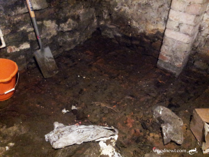
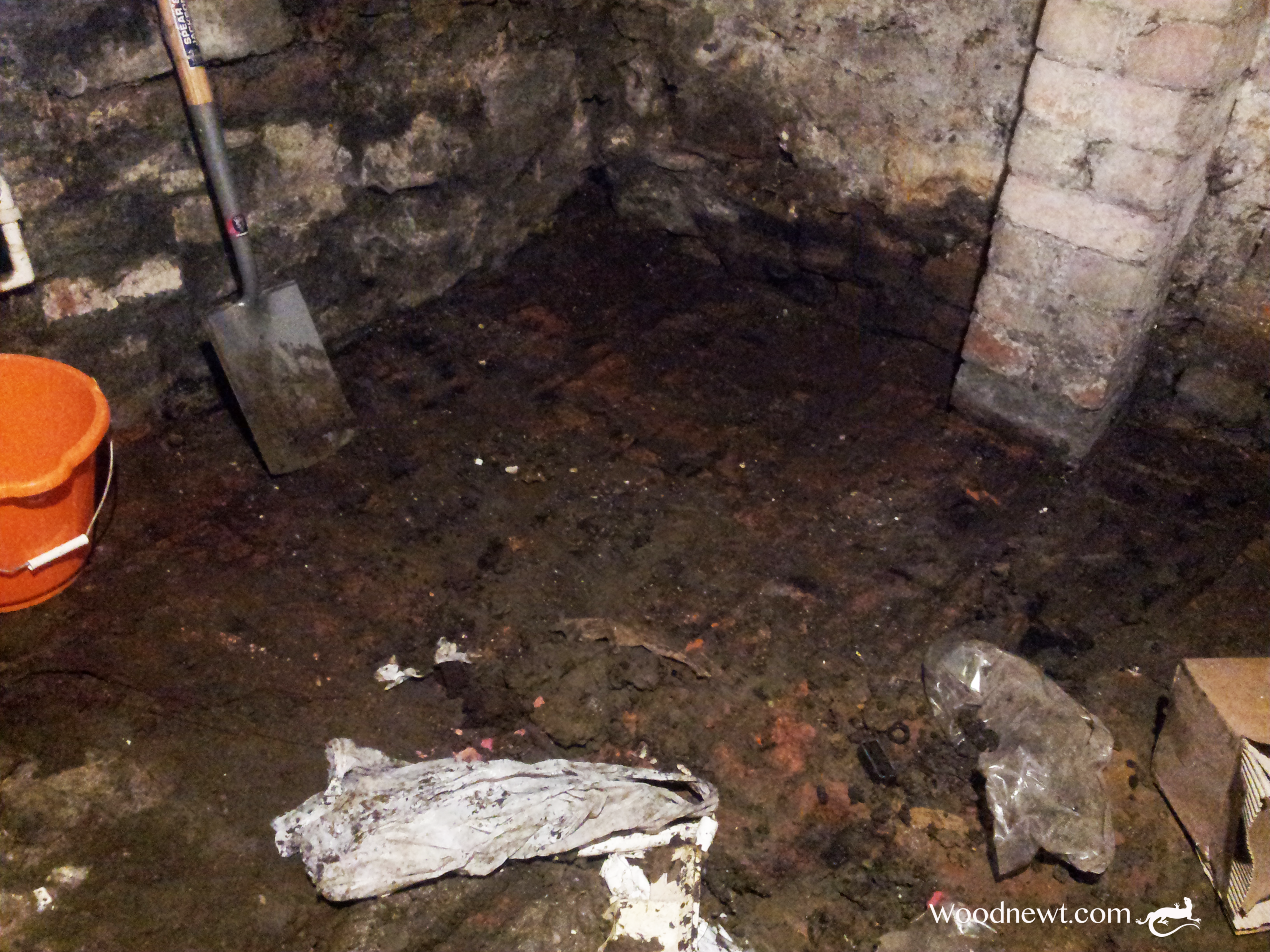
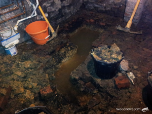
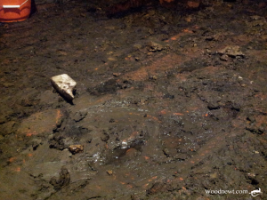
In the drier summer months the floor of the cellar was damp mud covering a brick floor. In the winter/wetter months the water pooled up to an inch deep and was only navigable by walking on pallets or other objects placed as ‘stepping stones’.  The walls are permanently damp and a single naked bulb glowed in the depressed darkness.

We discussed the option of tanking the cellar, but this was quickly rejected. Although it would be an excellent solution, it was far beyond the budget available.  The plan was simply to be able to make some use of the space available, not create a new room in the house.

The main problem was water. Neither of us was sure how water accumulated in the cellar, though we were aware that the cellar floor was about 5ft below ground level. Natural thought dictated that water rose up as the ground became saturated. Whatever the cause, the way to resolve the issue was to create a sump in the ground to collect the water and pump it out. 

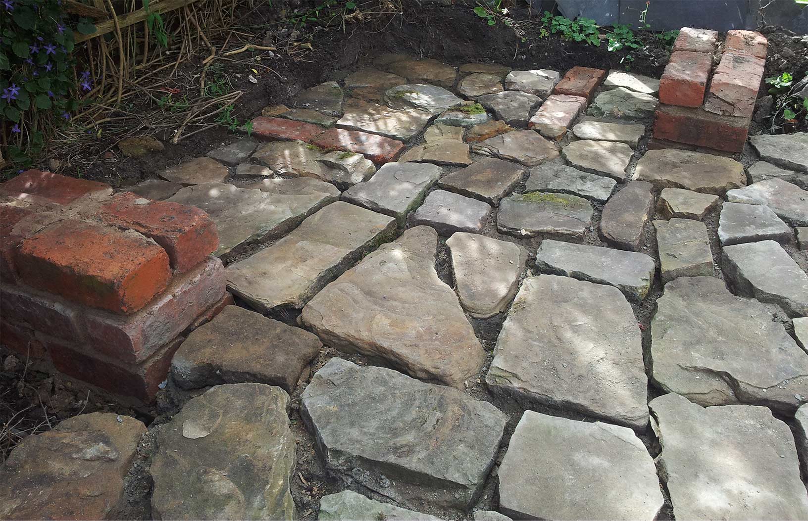
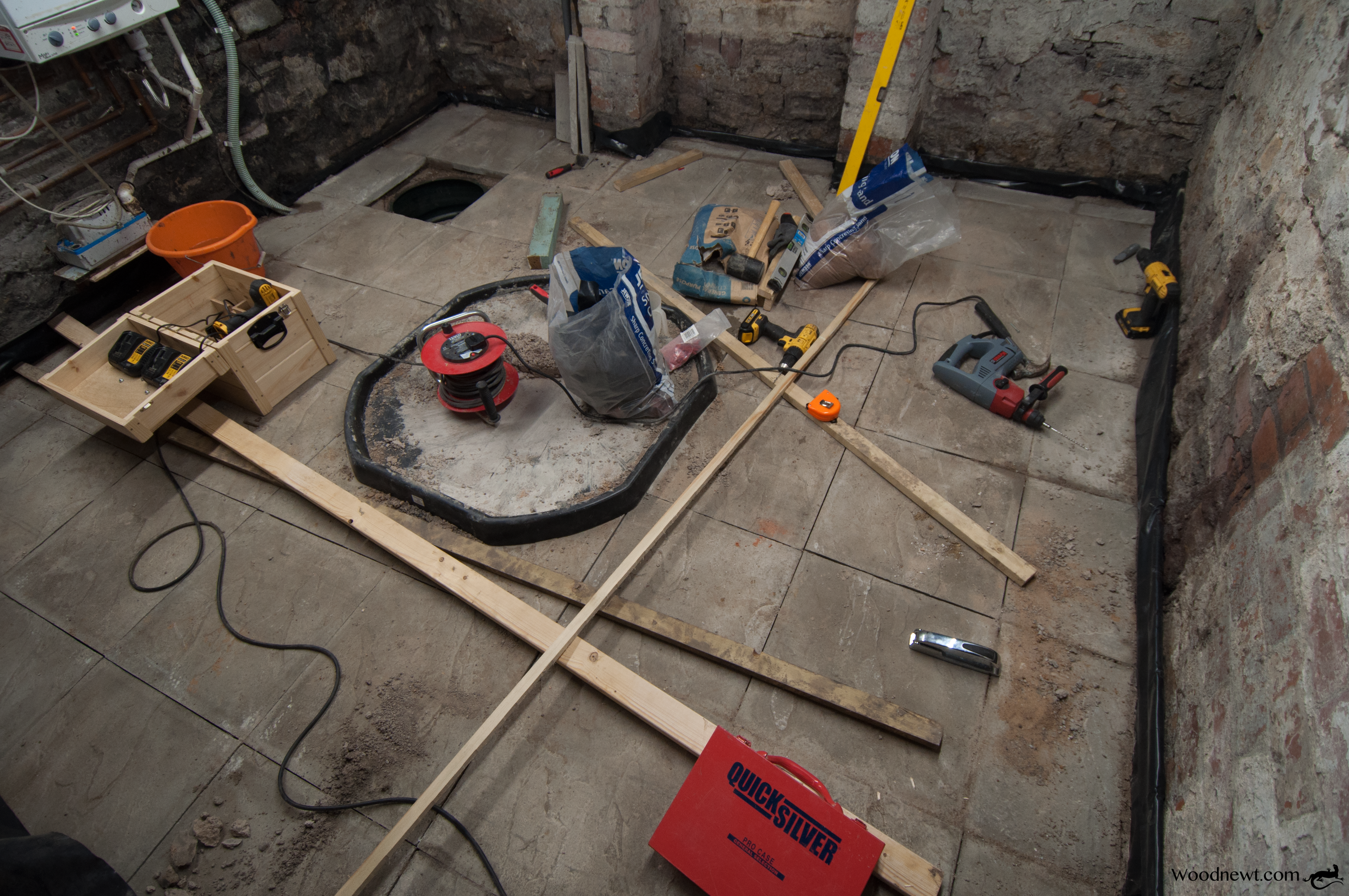
The first task was to clear out the debris, mud and an old stone bench built on two brick pedestals from the cellar floor, the space that could be liberated from this darkness became apparent.

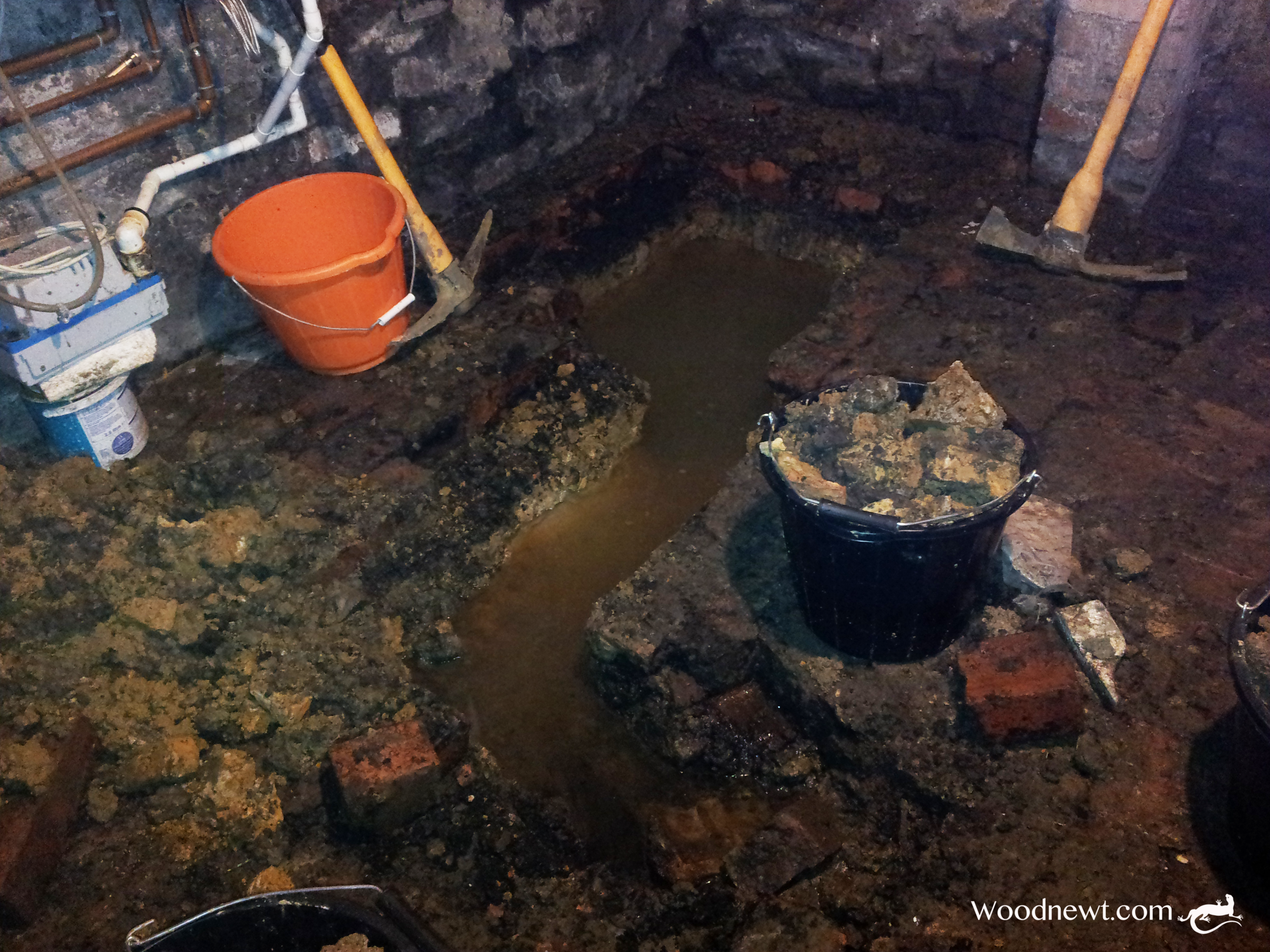
I started removing part of the brick flooring so as to sink a sump into the ground with the requirement to be able to house an electrically operated pump. We needed a sizeable sump, but purpose built plastic water tanks are very expensive.. and overly large. I sourced a 114 litre water butt to fit the bill. It had a lid and was large enough to house an inexpensive automatic drainage pump.

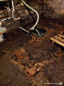
As I dug through the soggy surface into the clay I found that the clay was dry.. so the water was definitely not rising up through the ground. The hole that was dug however, did fill with water (slowly). Further Investigation found by taking some more bricks out, that water entered at the cellar floor level either under or through the brickwork of the walls, rather than upwards through the clay. To ensure the floor would drain of water, the sodden bricks needed taking up and drainage channels dug alongside the cellar walls, and then routed to the sump.

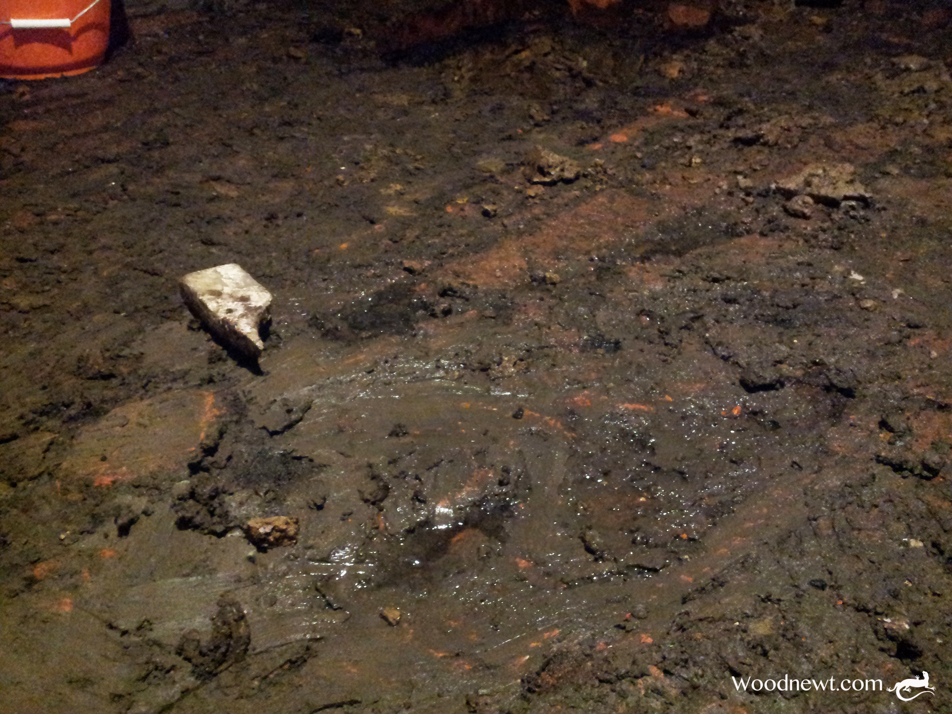
Through removing the stone bench and clearing the floor I noted some bricks laid as if covering a pipe, diagonally across the floor. I took these up for investigation, and found that water was draining in from the next door property at the point it came under the party wall. This source of water ingress would need addressing also, so the bricks above this pipe run were removed, locating a clay drainage pipe sunk almost 15” below the brick floor. it was set in a channel covered over with expanded foam blocks.  Removal of all these bricks to the opposite wall uncovered what appeared to be an open pipe sitting directly above the drainage pipe. I dug with my hands into the rubble and mud at the opening of the pipe to investigate, at which point the water that was sitting in the cellar drained out of the cellar via the pipe I had cleared.

Things were becoming clearer. This house was the last of a terrace of five, I took a walk to the opposite end of the terrace, and there was an inspection cover to what appeared to be the same pipe. it seems that water was tracking along this pipe channel and with the pipe above the drainage pipe exiting the building having silted up over the years, the water was unable to drain quickly. and would fill the cellar. The water ingress from the base of each of the four walls exacerbated the problem somewhat.

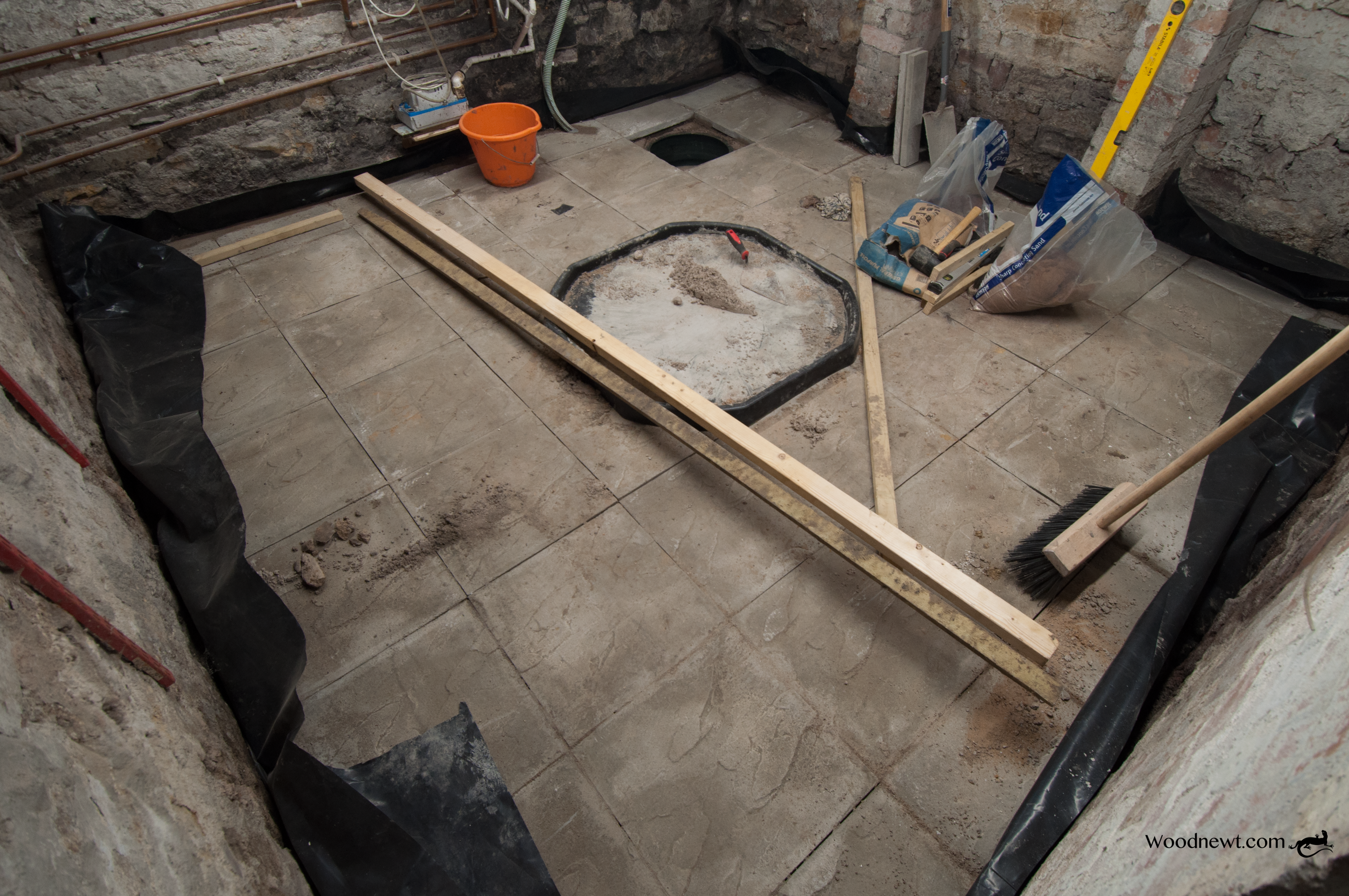
Now I understood the issue, a resolution could be offered. 1) take up all the bricks 2) dig out and level the floor 3) dig the hole for the sump, 4) dig channels along the walls 5) dig radial channels from them to the sump pit. 6) install the plastic sump (with holes drilled to allow water to enter). 7) infill channels with large hardcore allowing drainage 8) infill around the sump with large hardcore allowing water to enter  9) cover large hardcore channels with 20mm gravel  10) fit automatic float activated pump 11) lay heavy duty damp proof membrane 12) lay alternative floor.

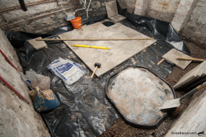
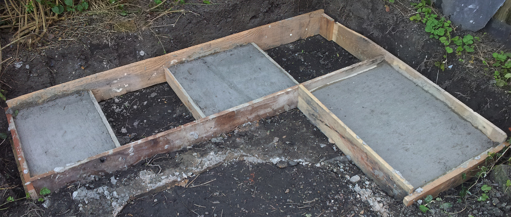
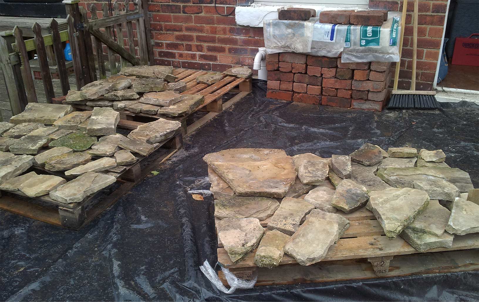
We had options for the floor. The house next door had a sump fitted a number of years ago and a decking floor installed. If installing a decking floor, we would lose about 5 inches of headroom, I suggested a concrete flag floor, essentially an indoor patio, moisture would not affect it, and additionally, we would only raise the floor about 2.5 inches. With removal of the old brick floor and some levelling of the floor before laying the concrete flags, we would gain up to a couple of inches of headroom (and be able to stand upright!).

We discussed what use the cellar would be put to, and reducing its elevated humidity and moisture levels and how that would affect usage. Sealing any ventilation is a bad idea, causing significantly more problems than one might solve. There are several air bricks serving the cellar area and the lower quarter of the walls get a little damp, so maintaining a low humidity cellar was not going to be cost effective.

Before getting to work down there, I needed more lighting, I took out the single 60 watt light fitting, replacing it with two 5ft LED battens. the stairs leading to the cellar was not lit, so I also added a pendant light fitting to serve that area, as it is nice to see where the steps are!

The pump would need power, and additional sockets would be handy. I noted that the consumer unit had a spare circuit on the RCD (Residual Current Detection) bus. so added a ring for the cellar, adding two twin gang sockets in the cellar and one at the top of the cellar steps. An electrician checked my work and wired my ring in to the consumer unit.

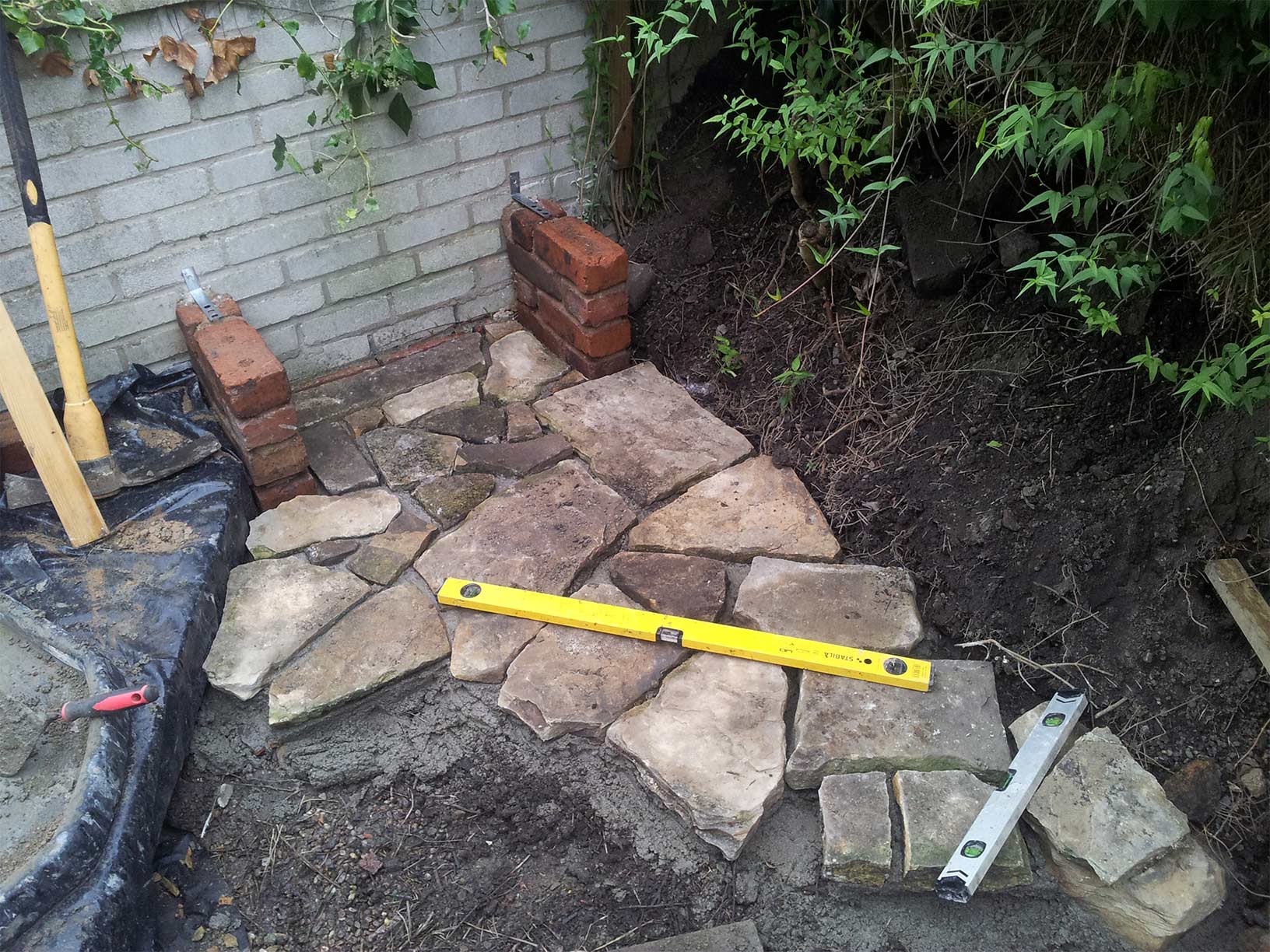
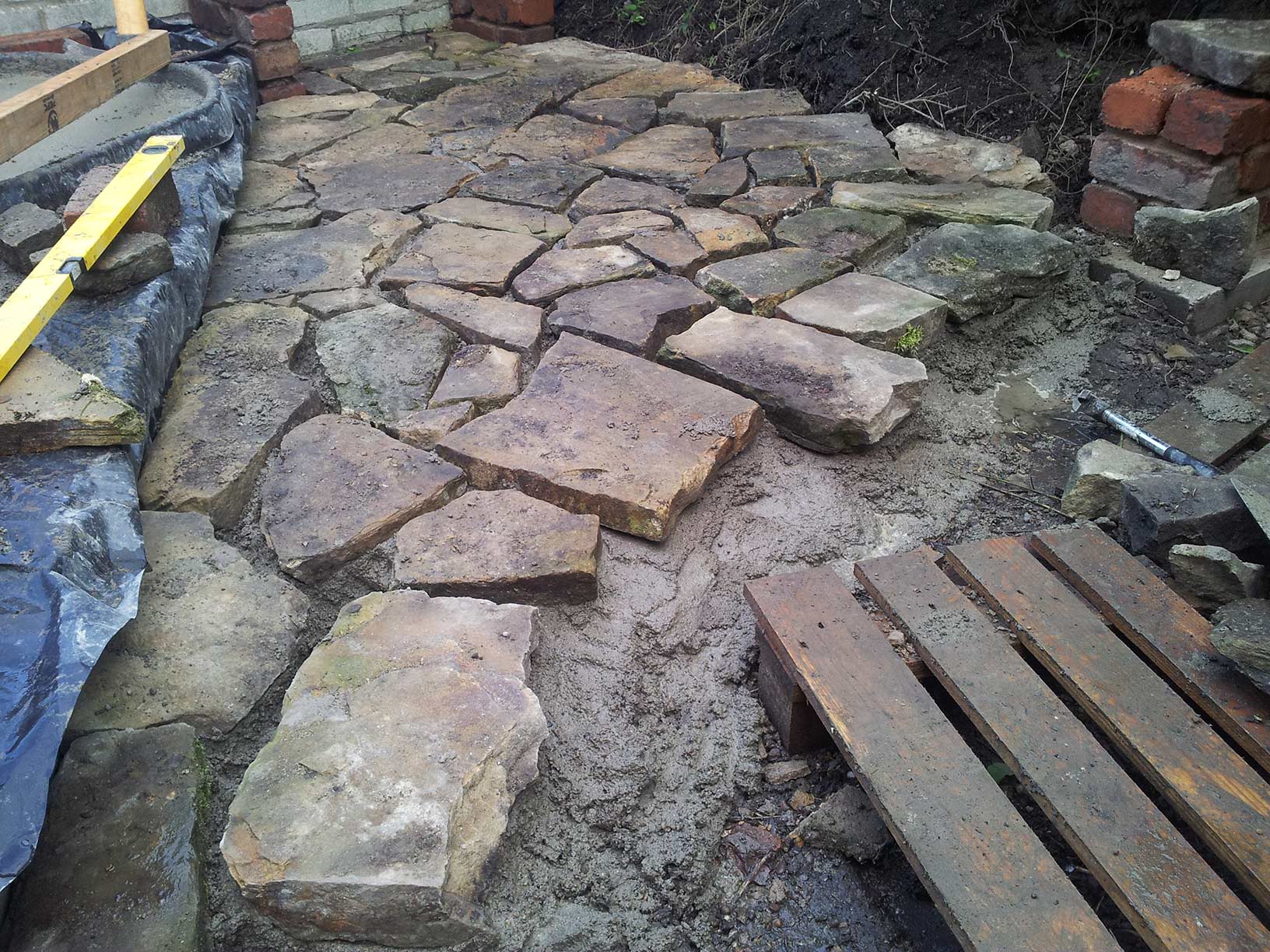
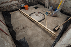
All digging and hardcore filling was completed along with the fitting of the sump. The pump was fitted bolting it to a concrete slab before lowering into the sump to ensure stability in use and allowing the float to function unhindered. the outlet pipe was routed out close to the cellar wall. The DPM was then laid, and starting from the sump, the flag floor was laid on a 6 to 1 mix of sharp sand and cement.

My friend wanted to paint the walls white to brighten it up. Unhappy with the old lime wash currently on the walls leaving powdery white marks on clothing as you brush against the walls going down the steps into the cellar. He wanted to paint the walls with a proprietary product. I did some research, as did he. My conclusion was to paint it again using lime wash. There are paints out there that claim breathability in damp conditions, but these were seriously expensive. Also, they are designed for walls that have a little damp, but the expectation for this cellar is that the walls will always be damp. After reading up on how experienced decorators viewed the proprietary paints and problems encountered, we opted to repaint the cellar with lime wash. To remove the problem of white powder marks, the walls entering the cellar (which are dry) were painted with an exterior wall paint.  Some parts of the lime wash took some time to dry, but the bright white walls from just three coats is rather impressive. at about £15 for a bag of hydrated lime to do the job, painting the walls would have been about 7 times the cost. Lime washed walls only become powdery with age, so a single re-coat every five years should keep it in check.

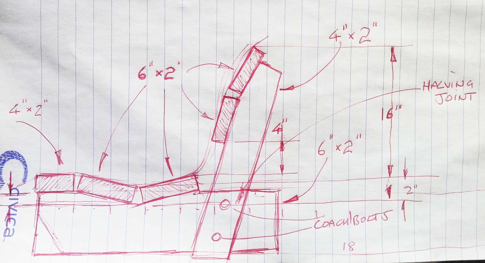
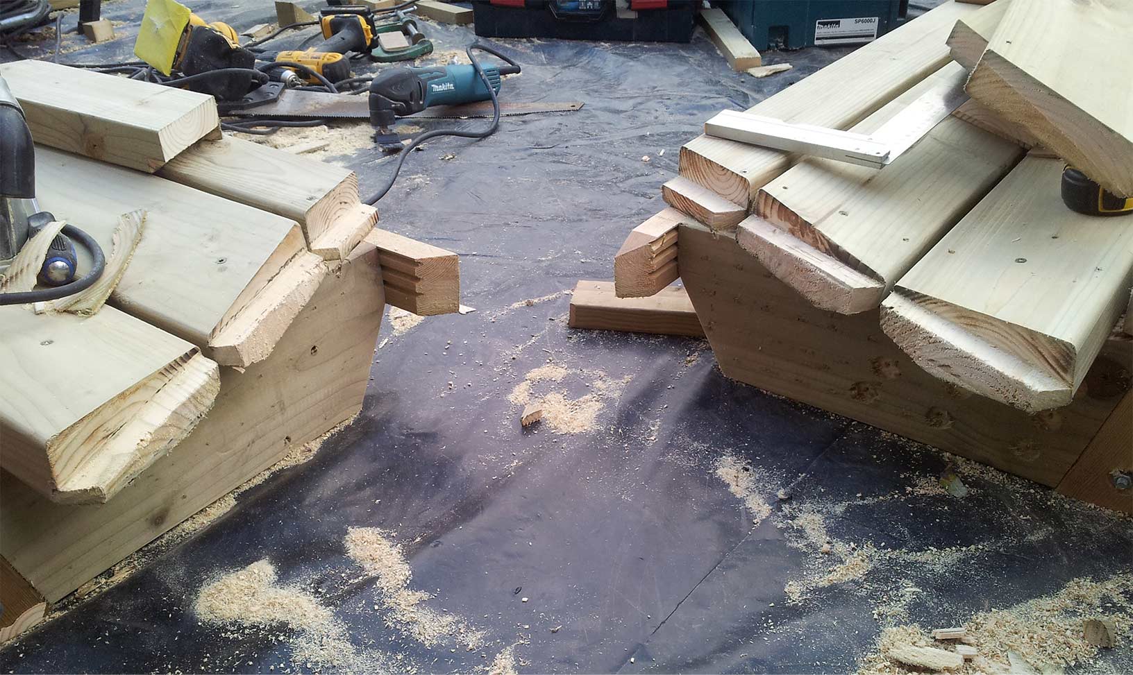
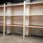
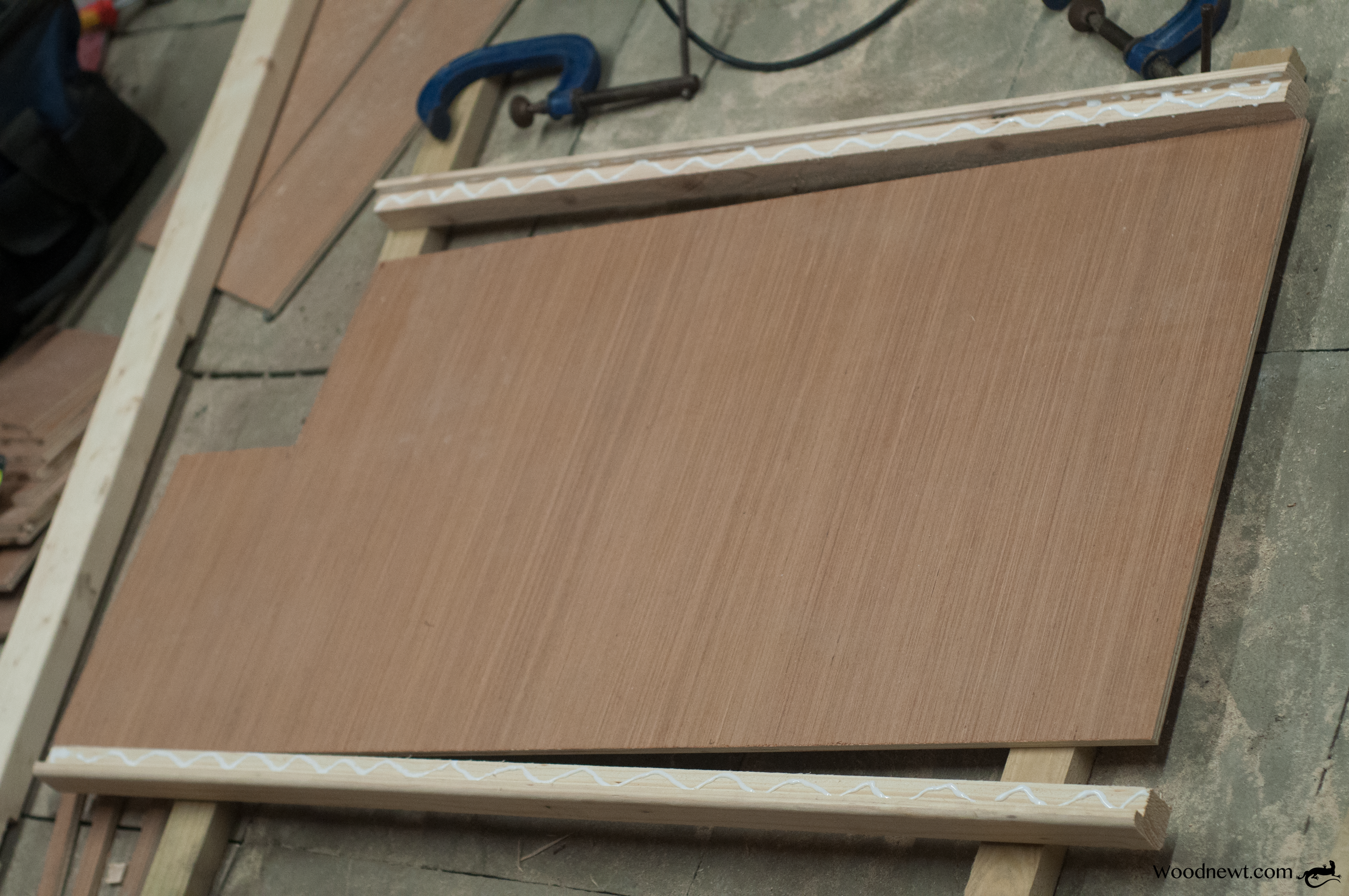
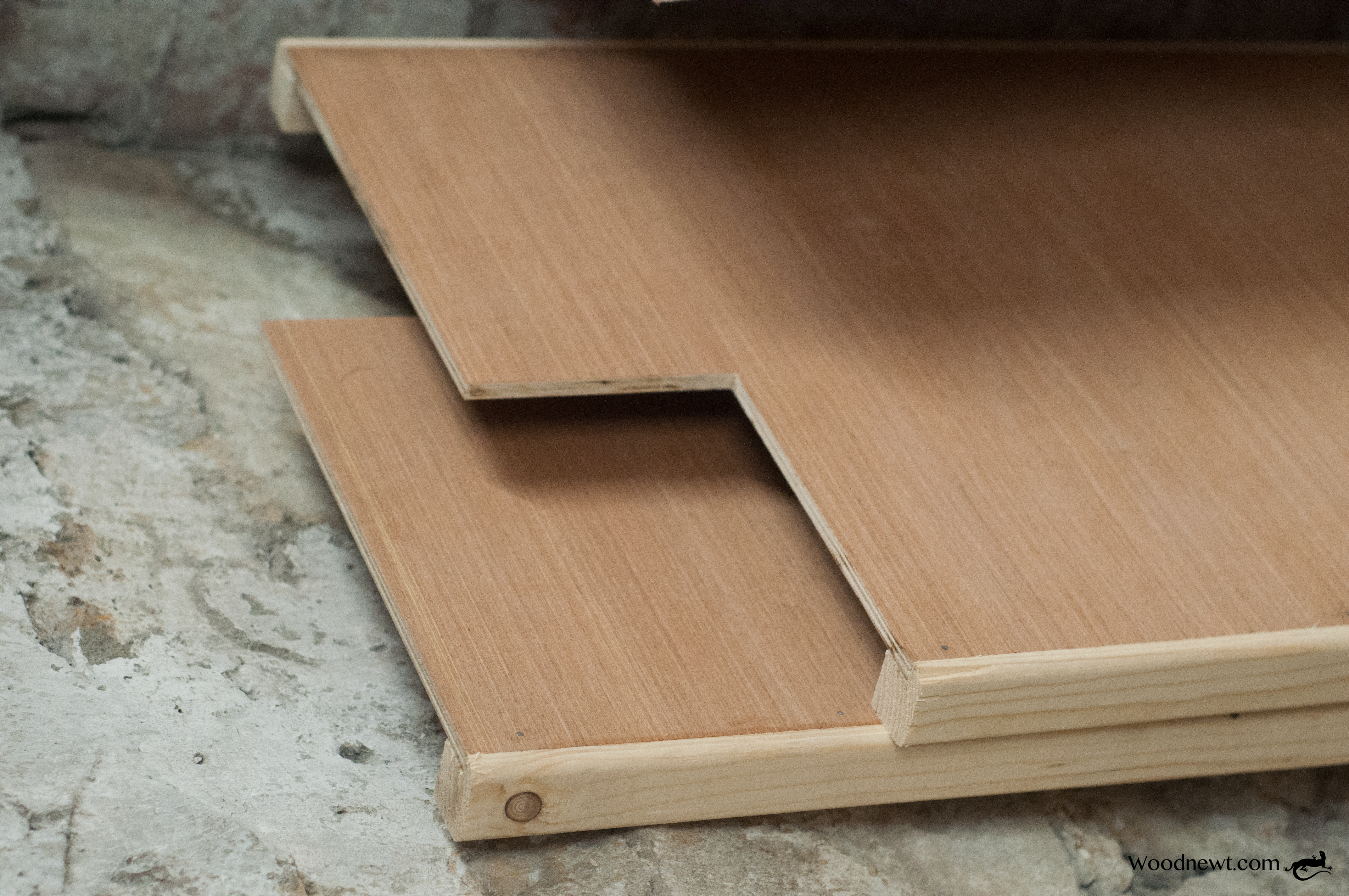
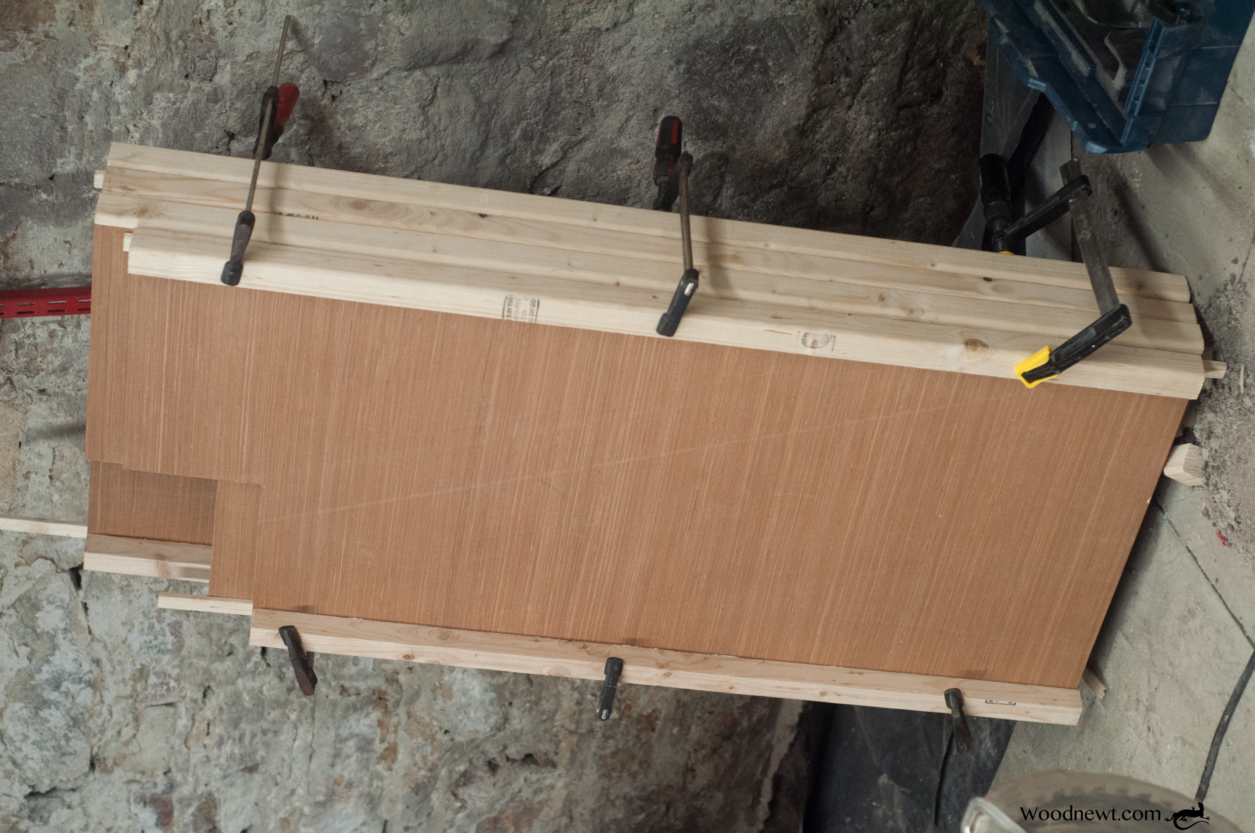
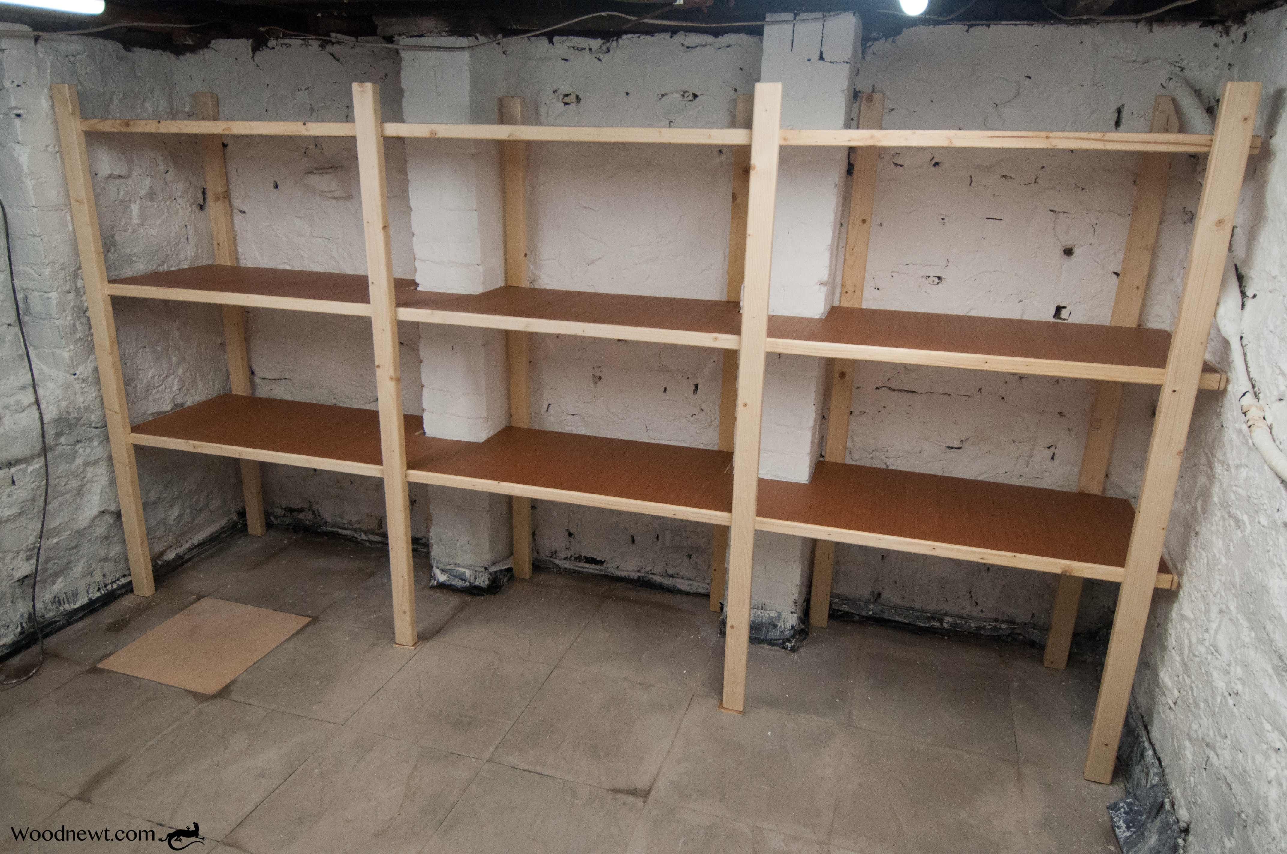
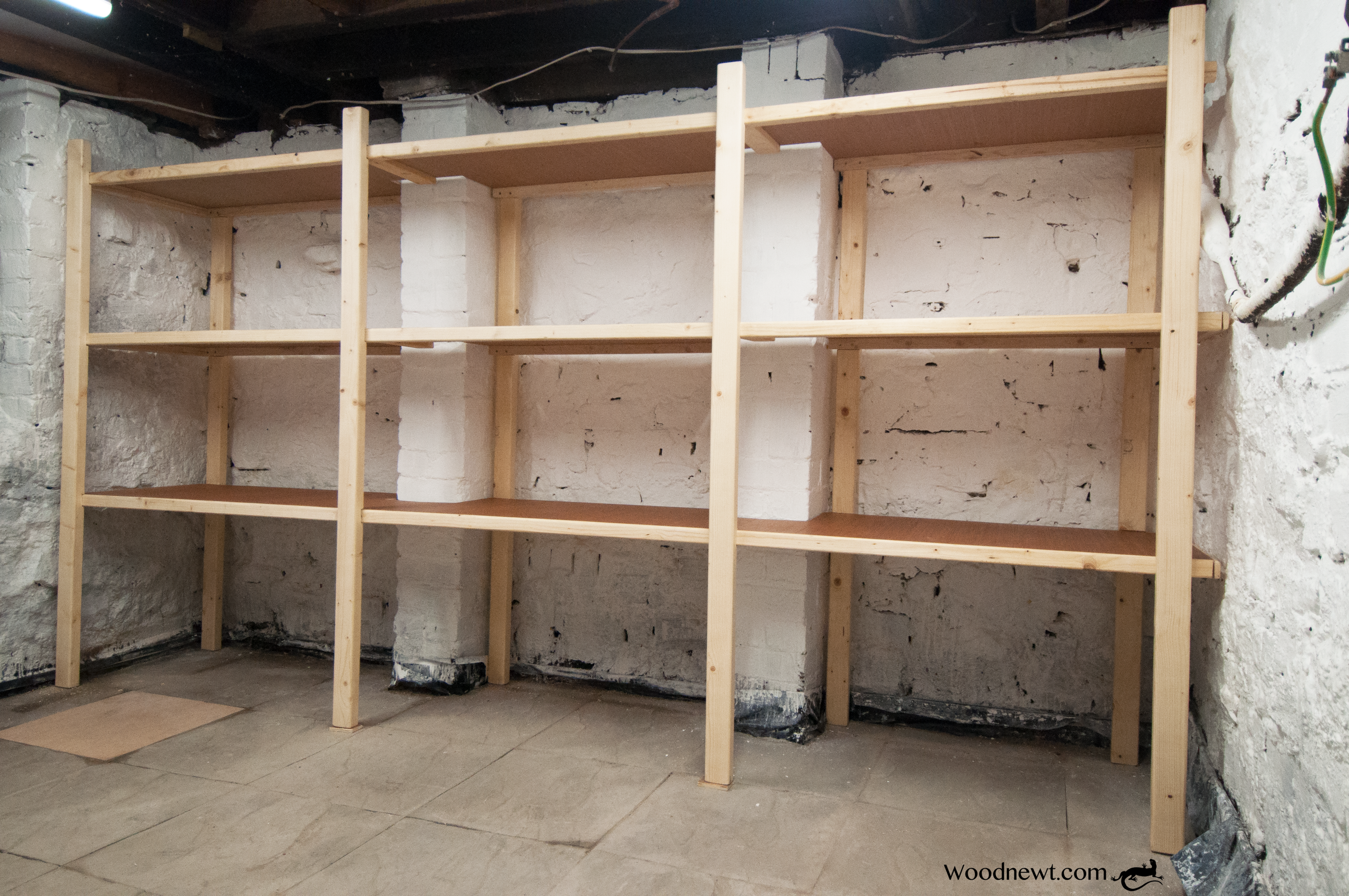
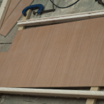
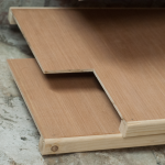
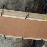
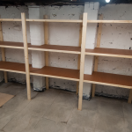
With the floor down, pump working like a dream and the walls painted, I could design and build the shelving system. Using 9mm hardwood faced ply rebated into nine frames manufactured from CLS (Canadian Lumber Standard) timber these were joined in sets of three with cutouts to fit around the  chimney breast foundation. these are then supported by and fixed to ten 3”x 2” CLS posts, notched to accept the shelving, giving improved load bearing ability. Prior to assembly they were painted with a water based satin varnish. When in position, the racking was secured to the wall with six brackets.

The hatch covering the sump is made from 18mm hardwood faced plywood. 

On completion, the feel of the cellar is bright and airy, it feels dry and smells fresh. The floor is solid and level and headroom has improved. The space is now served with extra lighting and has power sockets enabling a spot of DIY/hobby work down there. The wall of shelving allows other rooms in the house to be cleared of rarely used items, allowing the household to function with more space.

A great result!!